

Pumps used in fire suppression systems are essential components in improving building safety, mitigating property loss, and most importantly, mitigating the loss of life. Like the function of the human heart in creating fluid pressure and flow within the body for vital organs and other muscles, the fire pumps provide a similar function for a building’s fire suppression system.
The pumps create the required pressure and flow needed to satisfy system requirements. These pumps are designed and specified according to prescribed requirements and various international standards.
Fire pumps increase system water pressure and create the flow required to transfer water from one station to another. Calculating the system’s required flow and pressure are vital factors for selecting the proper pump size and capacity.
- Fire pumps are used in almost every commercial building, factory, multi-family residential facility and warehouse to protect and save life and property.
- The selection of a fire pump is crucial.
- Local and international standards ensure that building protection systems have adequate fluid pressure and flow to operate effectively.
- Pumps not appropriately designed, detailed and selected will consume more energy and require frequent maintenance.
Types of fire pumps
Positive displacement pump
With positive displacement pumps, liquid flows into the pump as the cavity on the inlet side expands, and the fluid flows out of the outlet as the cavity collapses. The volume is constant through each cycle of operation and is determined by the speed of rotation and the volume of the piston or rotor. It is suitable for liquids with higher viscosity and pressures and can operate at lower flow rates. This pump is typically used in foam and watermist firefighting systems.

Images supplied by Author / Contributor
Centrifugal pump
Centrifugal pumps are extensively used with most fire protection systems due to their comparative simplicity of design, efficiency and capability of operating at a wide range of flows and pressures. For centrifugal pumps, the output pressure decreases as flow increases. Operating pumps create a low-pressure area at the eye of the impeller to draw fluid through the suction inlet and into the eye of the rotating impeller. Centrifugal force will then move the water through the impeller to exit from the pump’s outlet. Centrifugal pumps have a high safety factor and can produce a wide range of flows and pressures.

Images supplied by Author / Contributor
Jockey-booster pump
Jockey pumps, which are also referred to as booster or jacking pumps, are utilised to maintain a required pressure in the pump discharge line so that the main fire pump is not required to operate to meet small system pressure demands. The main fire pump will start operation when the jockey pump fails to meet the necessary system demand.
Types of centrifugal fire pumps and their benefit
Centrifugal fire pumps are the most common type of fire pump. There are several types of centrifugal pumps available to meet unique system requirements. These types include:
- Split Case: This type is the most common centrifugal fire pump used to support firefighting systems. Although called double suction pumps, this pump type only has one inlet. It is the impeller that has two inlets. Fluid that enters the pump inlet is split and then channelled to the inlet eyes of the impeller. As the name implies, the pump casing is horizontally split, meaning that it consists of two parts, namely an upper and a lower casing. Removal of the upper casing allows easy access to internal pump parts for inspection and maintenance. Another feature of this pump type is that the inlet and outlet openings are inline and opposed.
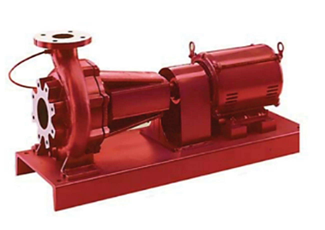
- End Suction: This pump type features an outlet that is inline and perpendicular to its inlet. They are of compact design and are ideal for where space is limited. These pumps have a lower range of water delivery than other pump types but also have a lower initial cost for most typical applications.
- Inline: These are close-coupled pumps that are installed with the motor orientated vertically. These pumps have a smaller footprint and will occupy less floor space. A benefit of selecting this type of fire pump is when there is a need to protect the motor and avoid flooding.
- Multistage, Multiport: Impellers mounted in series on a common shaft identifies this pump type. Each impeller is contained within its own housing and is called a stage. Each stage has a connection port that can be used to service different sections of the fire suppression system. Each stage has a greater pressure at the connection port than the previous stage.
- Where there is negative suction for below-ground water storage tanks, vertical turbine pumps are required. These types of centrifugal pumps do not require priming or positive suction.
The fire pumps discussed above can be driven in different ways. The most common drivers are diesel engines and electric motors.
Fire pump performance test issues
Prescribed performance tests and certification are mandatory throughout the various geographies of the Middle East by the numerous authorities having jurisdiction (AHJs) for every pump. These testing standards ensure that product manufacturers design fire pumps to certain quality, safety and reliability specifications. The standards provide guidance and instruction concerning fire pump product construction and performance. Certification of fire pumps to the prescribed requirements ensures that all fire pumps are tested to prove they achieve performance specifications to given standards, norms and codes. Testing assures end-users that during operation a fire pump will achieve its performance requirements in accordance with the test standards. The benefit is that before the pump is installed it will meet the requirements, and because of periodic testing it is ensured that the pump continues to meet the requirements.
The impeller is an influential pump component that directly impacts the head, flow, power and efficiency. During factory testing, if a pump does not meet the required head at rated flow, or flow at the rated head, then the impeller should be resized or modified to achieve the target. If the pump exceeds the rated head, the impeller diameter can be decreased according to the pump affinity rules. If a pump produces a lower or higher head, then impeller trimming or vane chipping can be performed as a remedy. If it consumes excessive power, an impeller polish will help to reduce power consumption by improving efficiency. Note that a vane-chipped impeller will cause power to increase at higher flow rates. A pump’s efficiency is inversely proportional to power; when efficiency is higher, power consumption will reduce. The impeller should always be dynamically balanced.
The pump casing is another critical part of achieving the power and power requirements. The casing internal flow passages must have a smooth surface finish and be free from any protrusions or craters.
Other elements of the pump are the packing and gland. The gland, when properly installed, is designed to allow a minimal amount of water to be consumed (leaked) for lubrication purposes. An improperly installed gland or worn packing can cause heavy water leakage, resulting in pressure loss.

Fire pump test method and conditions of attainment with standard
Fire pumps performance testing is typically in accordance with ANSI/CAN/UL448 – Underwriters’ Laboratories (UL) and Factory Mutual (FM) Standards, utilising ANSI/HI14.6 ‘Rotodynamic Pumps for Hydraulic Performance Acceptance Tests’. However, other standards exist. These fire pump test standards establish hydraulic performance acceptance grade (Grade 1U) through specified tolerance achievements, hydrostatic pressure, mechanical integrity and suction lift characteristics.
Operating speed is a critical component in fire-pump testing. The pump should meet the guarantee point against the acceptable tolerance grade as per ANSI/HI 14.6 at the required rotational speed. Some standards have a requirement for a pump to meet a specific head value while under a 15ft suction lift condition. Flow and total head development at various flow capacities should be achieved. Also, the peak power consumed for the acceptable tolerance grade shall be fulfilled.
A minimum of eight data points will accurately depict pump performance. The rated flow point shall be defined as a point that is within -5% and 0% of the flow rating and a second point within 0% and +5% of the rated flow.
Other performance requirements include that the shut-off head shall be below 140% of the rated head according to UL and FM standards. Performance data is to be recorded at a minimum flow of 50% of rated flow, and at 110% of rated flow, 130% of rated flow, 150% of rated flow, and at a maximum flow of the pump. At 150% of the rated flow, pump head shall not be less than 65% of the rated head. Additionally, the pump peak power should be below or equal to the power of the drive, test equipment should be properly calibrated if it is to meet the requirements listed in the standards.

Fire pump acceptance testing
The fire pump system design is additionally guided by various standards and provides a basis for validating the pump during testing and performance acceptance.
- NFPA 70 National Electrical Code for the installation of wiring requirements
- NFPA 13 for the installation of sprinkler systems
- NFPA 14 standard for the installation of standpipe and hose systems
- NFPA 15 standard for water spray fixed systems for fire protection
Fire pumps are installed, commissioned and accepted for life safety and building protection purposes based on NFPA 20 standard guidelines, requirements and demands, which refer to the above standards. A fire pump has three primary units: a pump, a drive and a controller. Pump drivers include electric, diesel engine-driven and jockey booster pumps.
Flushing and hydrostatic testing should be completed before the commencement of the fire pump test and operation activities. The flushing and hydrostatic testing procedures remove from inside the pump any foreign particle that may have entered the suction inlet, which could influence performance or cause damage to the impeller or casing. The hydrostatic static test helps ensure the durability, quality and safety of system pipes and fittings. This test helps detect underground and above-ground pipeline system leakage and is performed according to the NFPA 24 standard. The flow test ensures the fire pump performance head, flow and power are met according to the pump manufacturer-certified plot and datasheet.
The periodic inspection, testing and maintenance of fire pump systems are essential and undertaken per the local regulatory guidance documents that reference NFPA 25 standards for water-based fire protection systems.
The fire pump acceptance test should include shut-off head, rated head and peak power. While performing the acceptance test in the field, the manufacturer’s certified performance test results are compared and cross-verified with the on-site tested pump plot and datasheet. The certified fire pump performance curve is the factual record of the fire pump’s performance. It describes how the pump will operate in the field according to the manufacturer’s certified test curve. It is a point of reference to compare the fire pump against when it is in the field to ensure that the pump has not sustained damage during moving and setting up. The result of fire pump performance in the field should achieve the required fire protection demand.
For more information, go to www.emirateslaboratory.com
About the Author

Amirtharaj Arun, Senior engineer at DCD’s Emirates Safety Laboratory offers a comprehensive overview of the protocols and standards for bus fire suppression system testing.
